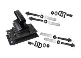
In addition to consistent clamp force ,shear and tensile strength ,the max-grip fasteners provides a unique locking-groove design,which ensure the application of different demands-reduce the rework and warranty claims.
Application on one-surface connection (sheet and other structure E.g box structure)
After special surface treatment ,this fasteners are highly anti-corrosion and qualified to fastening connection of different materials(Eg.Aluminum and steel,Non-metallic and metallic)
Basic Dimension

| Diameter | d | D | L1 | L | |||
| min | max | min | max | min | max | ||
| 5 | 4.98 | 5.23 | 7.01 | 7.26 | 3.86 | 4.27 | 19.94 |
| 6 | 6.65 | 6.99 | 9.35 | 9.65 | 5.21 | 5.72 | 25.84 |
| 8 | 8.43 | 8.79 | 11.89 | 12.14 | 6.76 | 7.06 | 32.64 |
| 10 | 9.98 | 10.44 | 14.05 | 14.30 | 8.00 | 8.31 | 35.74 |
| 12 | 13.44 | 13.82 | 18.90 | 19.15 | 10.54 | 11.13 | 38.86 |
| 16 | 16.81 | 17.40 | 23.65 | 23.9 | 12.88 | 13.84 | 43.43 |
Mechanical Properties
| Diameter | 5 | 6 | 8 | 10 | 12 | 16 |
| KN Shear | ≥12.4 | ≥22.7 | 35.8≥ | ≥49.3 | ≥89.6 | ≥126.7 |
| KN Tensile | ≥7.9 | 14.4≥ | ≥22.9 | ≥32 | ≥57.5 | ≥90.6 |
Hole Data
| Norminal Dia | 5 | 6 | 8 | 10 | 12 | 16 |
| Hole Dia | 5.3-5.6 | 7-7.4 | 8.8-9.3 | 10.5-11.1 | 13.9-14.8 | 17.5-18.5 |
Grip Range
| Type | Grip Range | |||||||||||
| Φ5 | Φ6 | Φ8 | Φ10 | Φ12 | Φ16 | |||||||
| min | max | min | max | min | max | min | max | min | max | min | max | |
| 3 | 2.4 | 4.0 | 2.4 | 4.0 | -- | -- | -- | -- | -- | -- | -- | -- |
| 4 | 4.0 | 5.6 | 4.0 | 5.6 | -- | -- | -- | -- | -- | -- | -- | -- |
| 6 | 5.6 | 7.1 | 5.6 | 7.1 | 4.8 | 7.9 | 4.8 | 7.9 | 6.4 | 9.5 | 6.4 | 12.7 |
| 8 | 7.1 | 8.7 | 7.1 | 8.7 | -- | -- | -- | -- | -- | -- | -- | -- |
| 9 | 8.7 | 10.3 | 8.7 | 10.3 | 7.9 | 11.1 | 7.9 | 11.1 | 9.5 | 12.7 | -- | -- |
| 11 | 10.3 | 11.9 | 10.3 | 11.9 | -- | -- | -- | -- | -- | -- | -- | -- |
| 12 | 11.9 | 13.5 | 11.9 | 13.5 | 11.1 | 14.3 | 11.1 | 14.3 | 12.7 | 15.9 | 12.7 | 19.1 |
| 14 | 13.5 | 15.1 | 13.5 | 15.1 | -- | -- | -- | -- | -- | -- | -- | -- |
| 16 | 15.1 | 16.7 | 15.1 | 16.7 | 14.3 | 17.5 | 14.3 | 17.5 | 15.9 | 19.1 | -- | -- |
| 17 | 16.7 | 18.3 | 16.7 | 18.3 | -- | -- | -- | -- | -- | -- | -- | -- |
| 19 | 18.3 | 19.8 | 18.3 | 19.8 | 17.5 | 20.6 | 17.5 | 20.6 | 19.1 | 22.2 | 19.1 | 25.4 |
| 22 | -- | -- | -- | -- | 20.6 | 23.8 | 20.6 | 23.8 | 22.2 | 25.4 | -- | -- |
| 25 | -- | -- | -- | -- | 23.8 | 27.0 | 23.8 | 27.0 | 25.4 | 28.6 | 25.4 | 31.8 |
| 28 | -- | -- | -- | -- | -- | -- | 27.0 | 30.2 | 28.6 | 31.8 | -- | -- |
| 31 | -- | -- | -- | -- | -- | -- | 30.2 | 33.3 | 31.8 | 35 | 31.8 | 38.1 |
After Installation
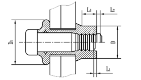
| Diameter | L1 | L2 | L3 | D | D1 |
| min | max | min | max | Ref | |
| 5 | 0.8 | 2.4 | 2.8 | 6.6 | 7.7 |
| 6 | 2.4 | 4.0 | 8.8 | 10.3 | |
| 8 | 1.2 | 4.4 | 4.8 | 11.0 | 13.1 |
| 10 | 4.4 | 5.2 | 12.9 | 15.4 | |
| 12 | 1.6 | 4.4 | 7.5 | 17.4 | 21.4 |
| 16 | 2.0 | 7.9 | 10.3 | 22.1 | 26.4 |
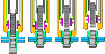
Installation Sequence
